Create My Data
Within “My Data” you control the full lifecycle of TianGong LCA datasets. This guide breaks the work into three stages—Preparation → Build datasets → Data validation & publish—to minimise rework and keep references consistent.
Before you start
Common rules
- Language fields: Whenever a field offers multiple languages, the English input is mandatory. Match the language selector to the content you enter.
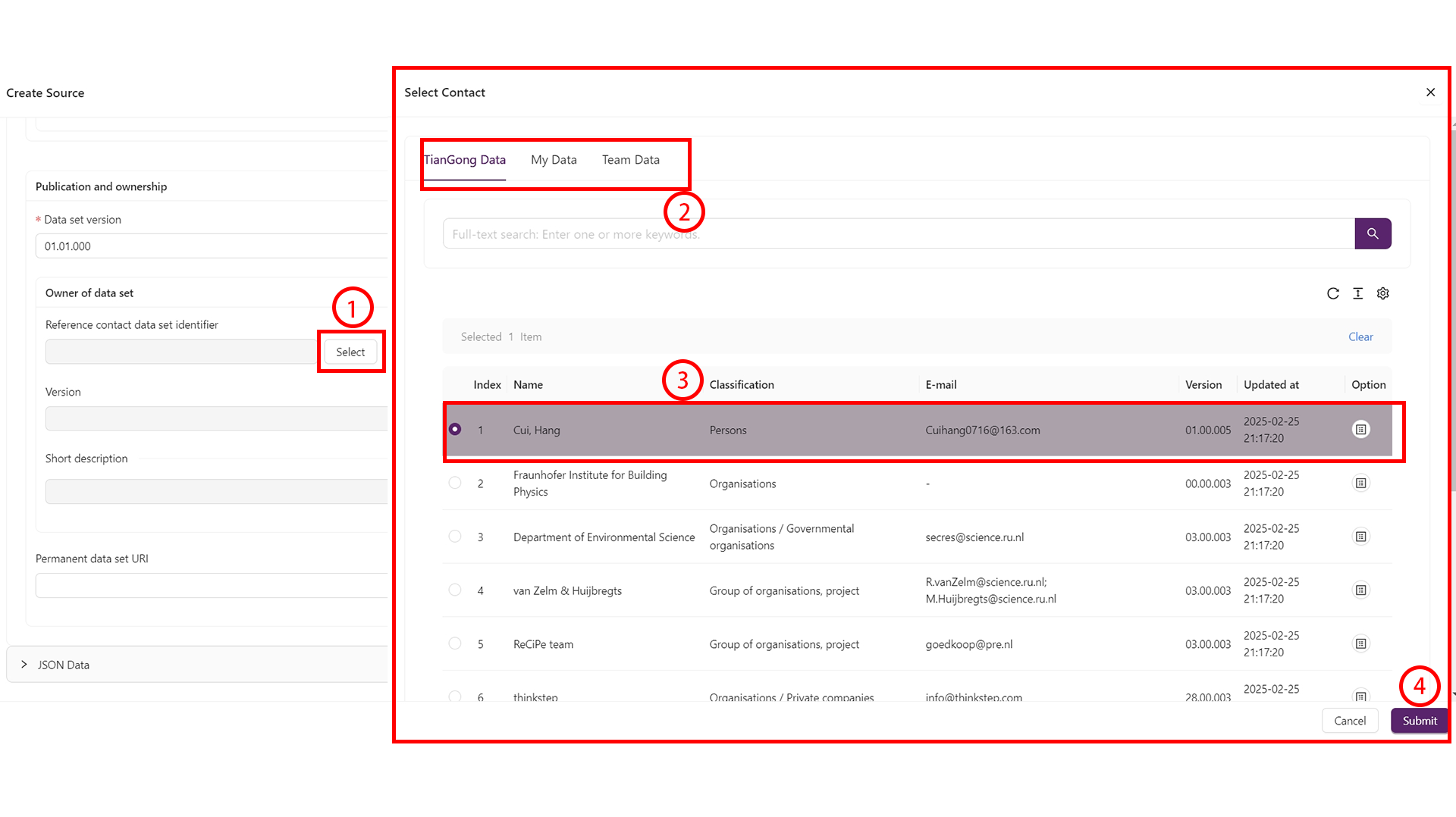
- Selection panels: For fields such as “Dataset format” or “Compliance system name”:
- Click the “Select” button next to the field.
- Use the tabs to switch categories.
- Tick the desired row (highlighted in purple).
- Click “Save” to confirm and exit the panel.
- Versioning: Fill in the version number first and save a draft. Continue editing afterwards and save frequently to prevent data loss.
Recommended preparation order
To ensure every reference exists when you start modelling, prepare these items first:
- Contacts: Identify responsible people and their email addresses.
- Sources: Gather literature, reports, or survey materials; upload any supporting files.
- Unit groups & flow properties: Reuse standard definitions whenever possible. Only create new ones after team review.
- Flows: Define flows with the correct unit groups and properties so that processes can reference them immediately.
Once the groundwork is complete, move on to processes and models.
Build datasets
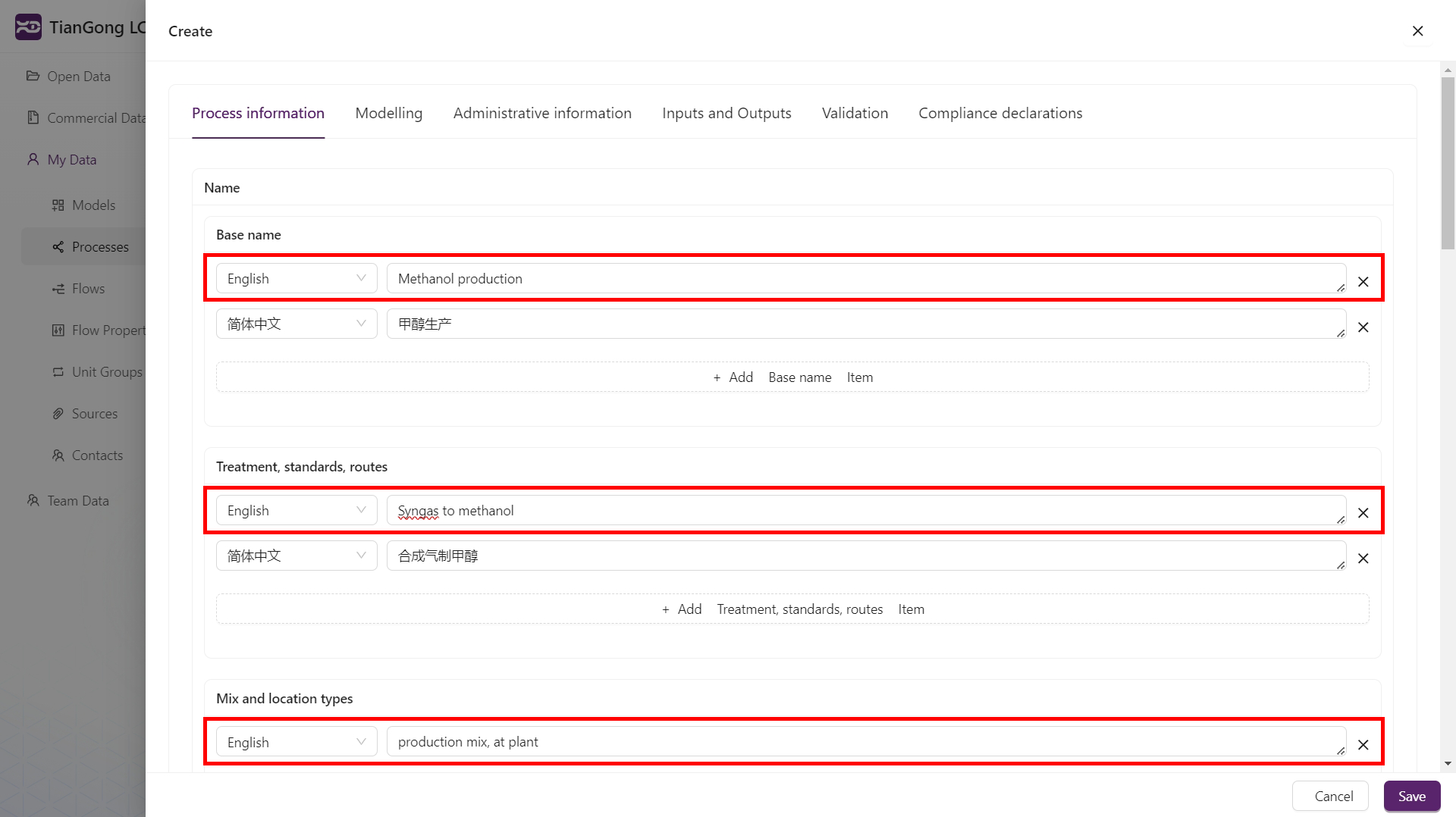
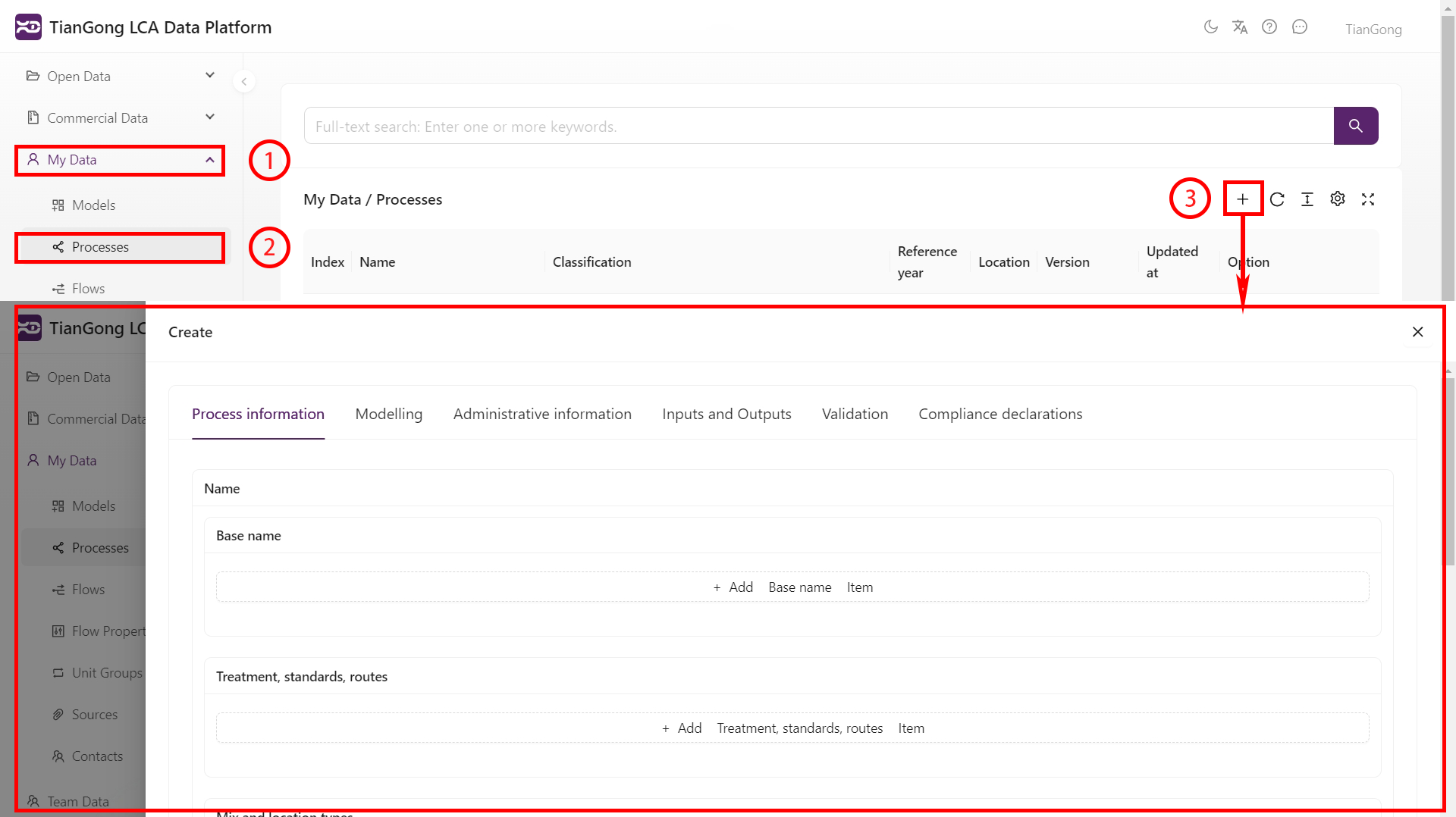
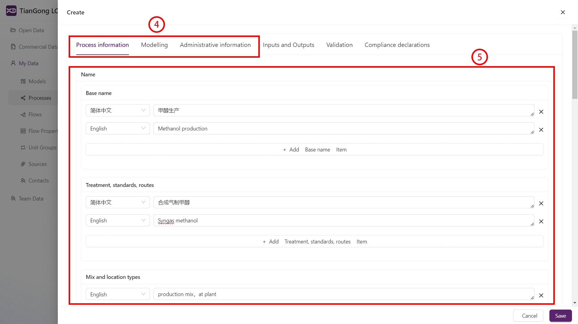
Create a process
- Open My Data → Processes and click
+. - Complete the “Process information”, “Modelling information”, and “Management information” sections.
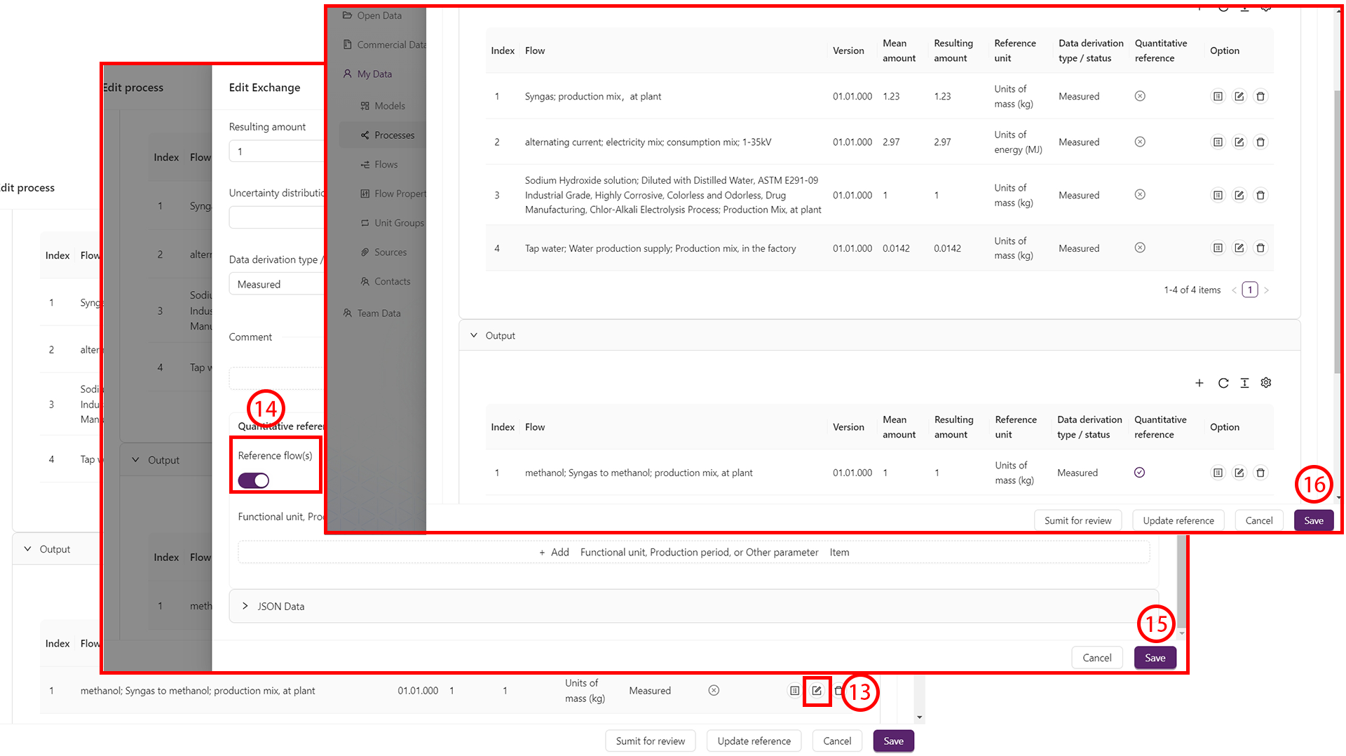
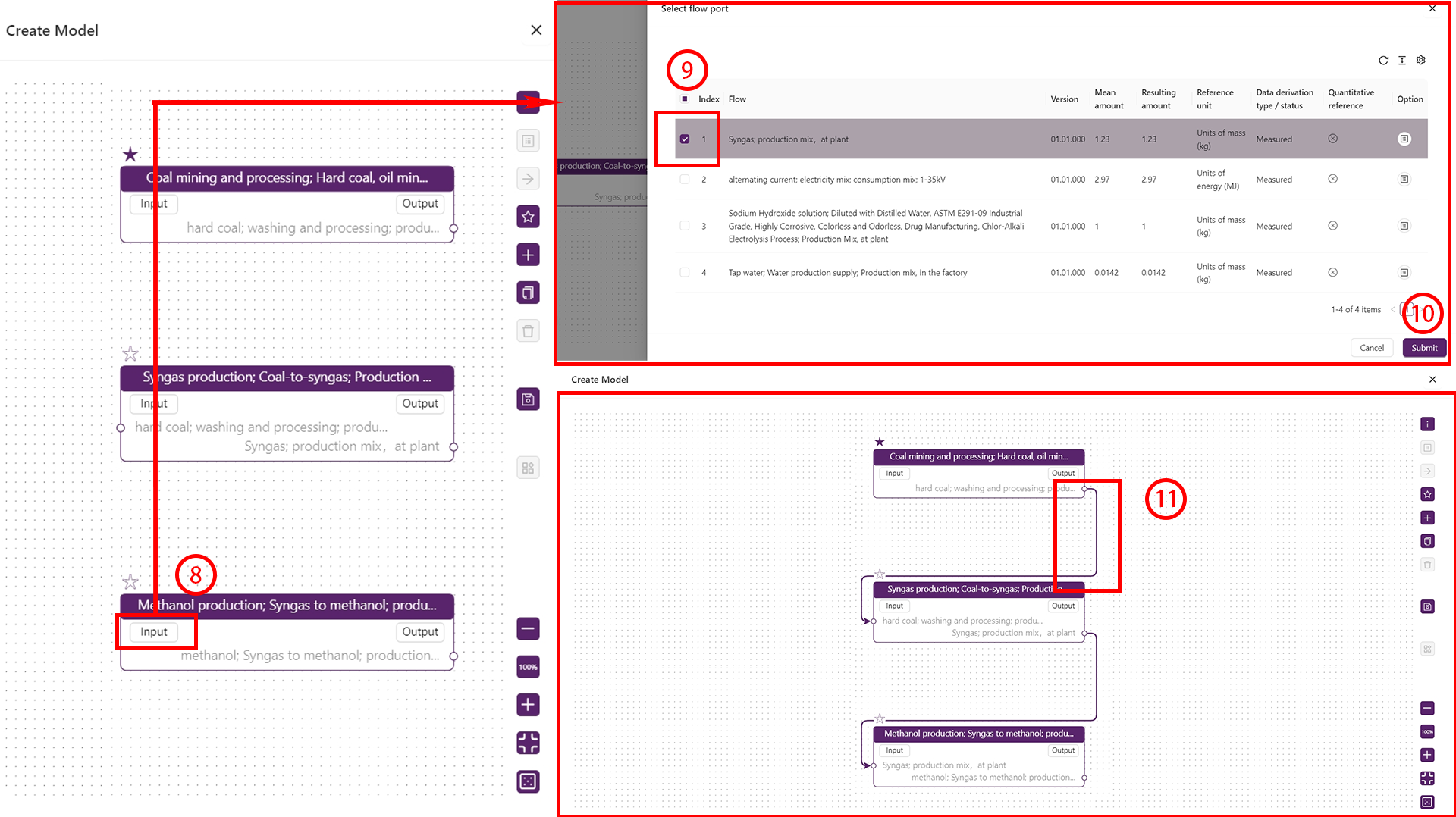
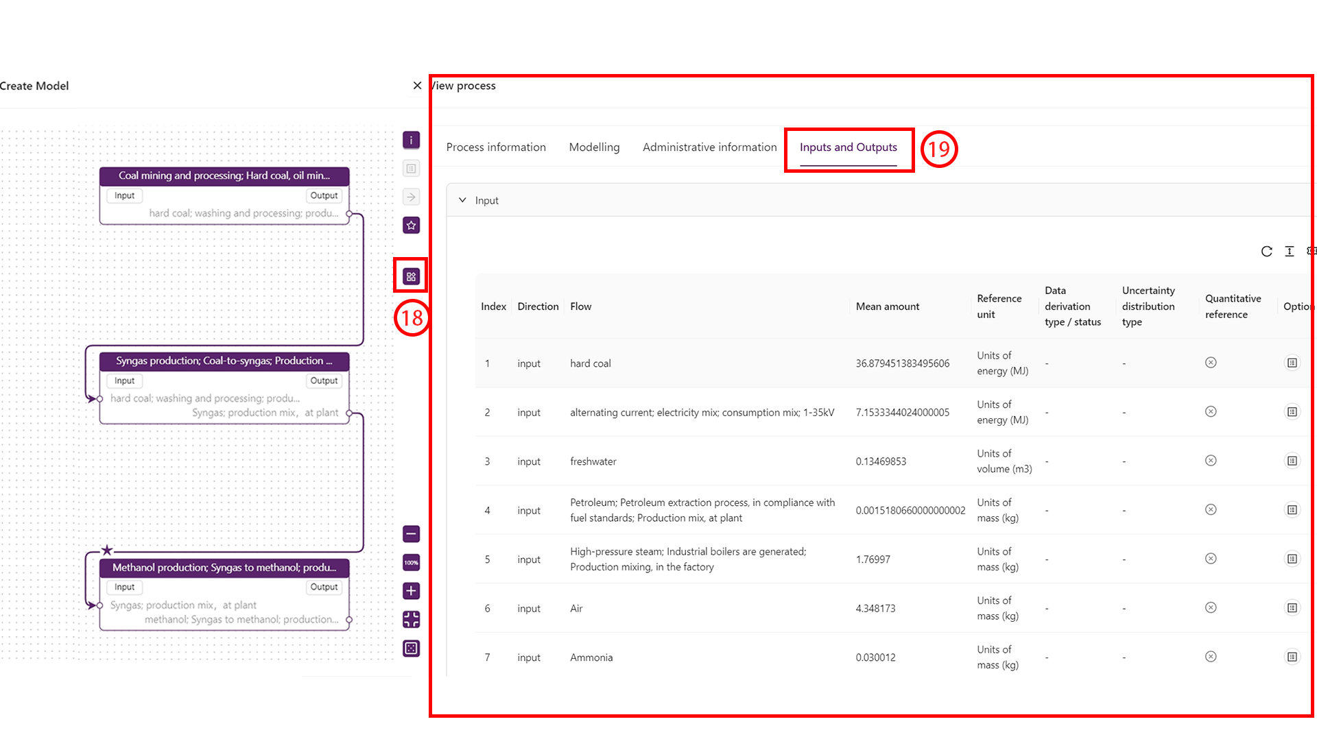
- Switch to Inputs & Outputs to add flows:
- Click
+to reference an existing flow or create a new one (see Create a flow). - Enter the quantity and unit; perform conversions if needed.
- Save and repeat until all flows are listed.
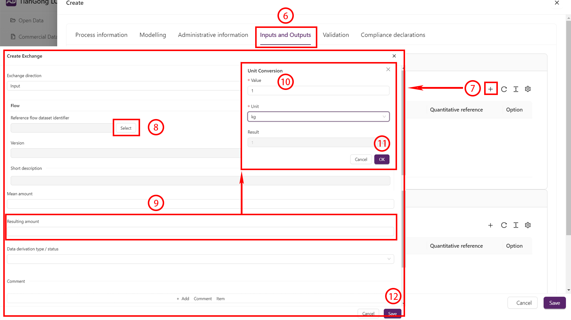
- Click
- Designate the main output as the Reference flow and save.
- Click Save at the bottom to store the process configuration.
Create a model
- Open My Data → Models and click
+. - Use the node selector to add the processes that belong to the model.
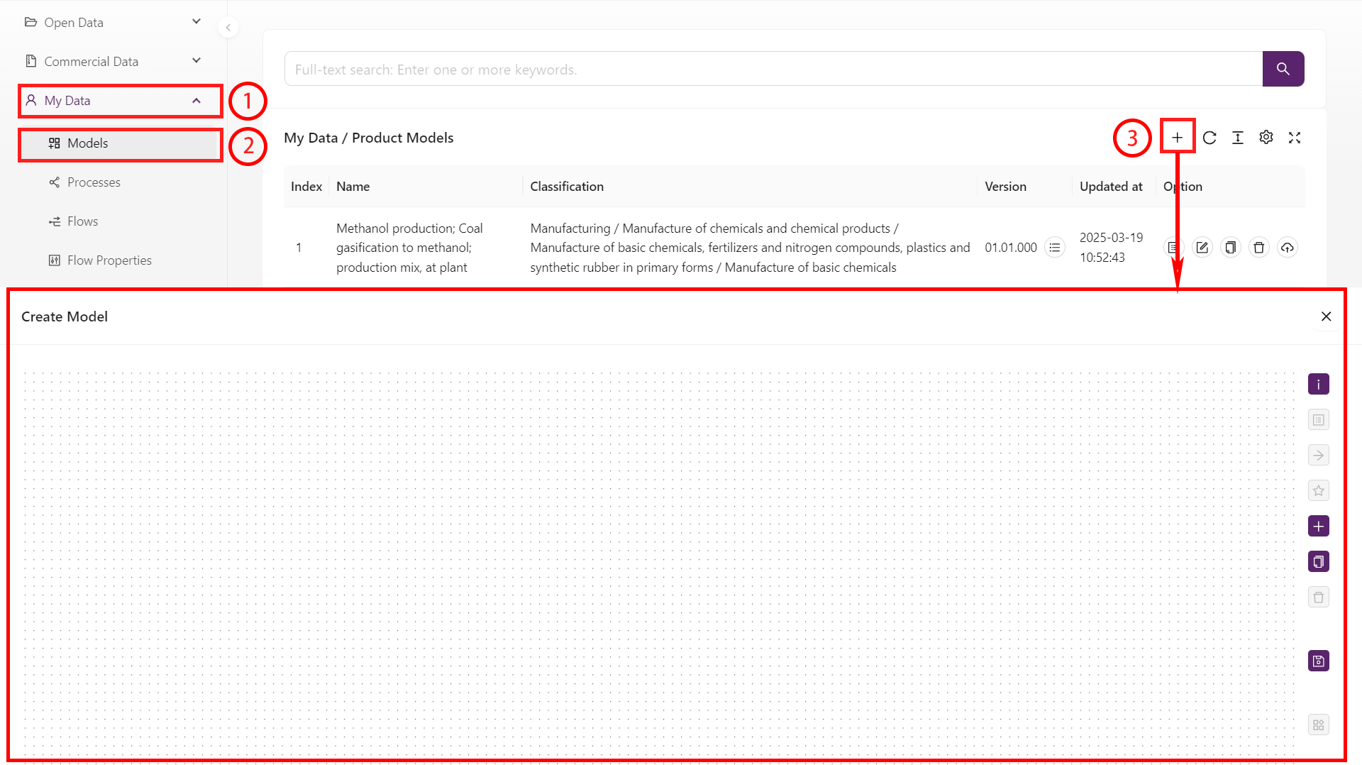
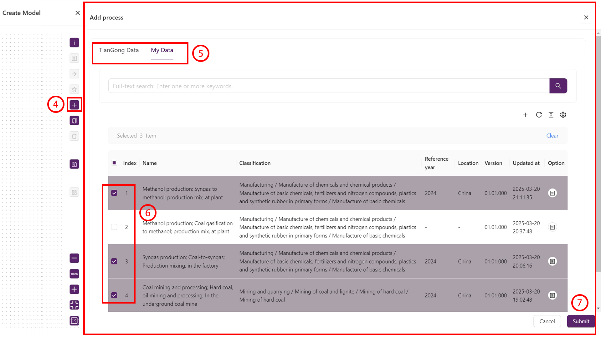
- For each node, open Inputs/Outputs and connect the required flows.
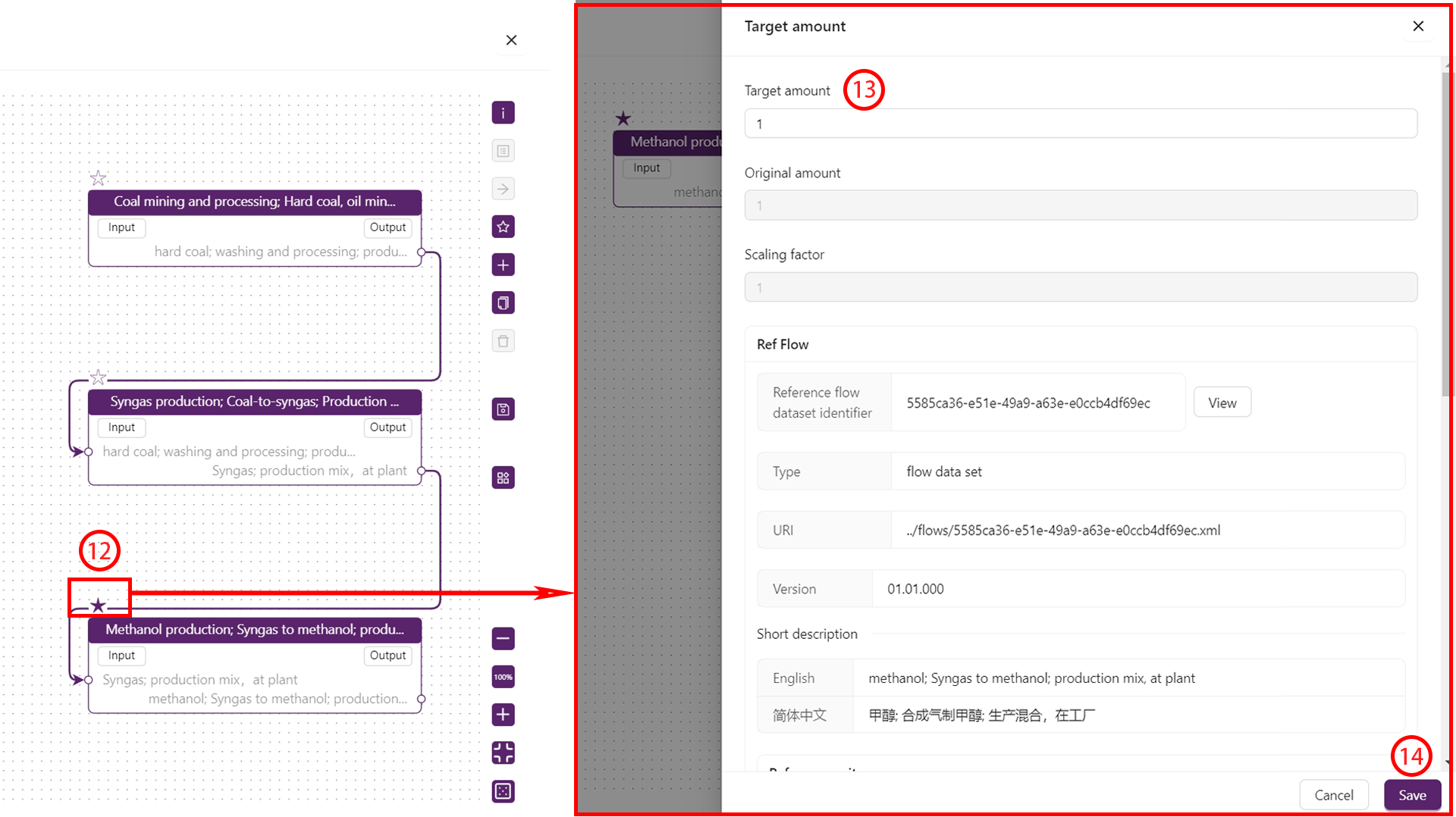
- Arrange the nodes, set the reference process, and specify the reference flow quantity.
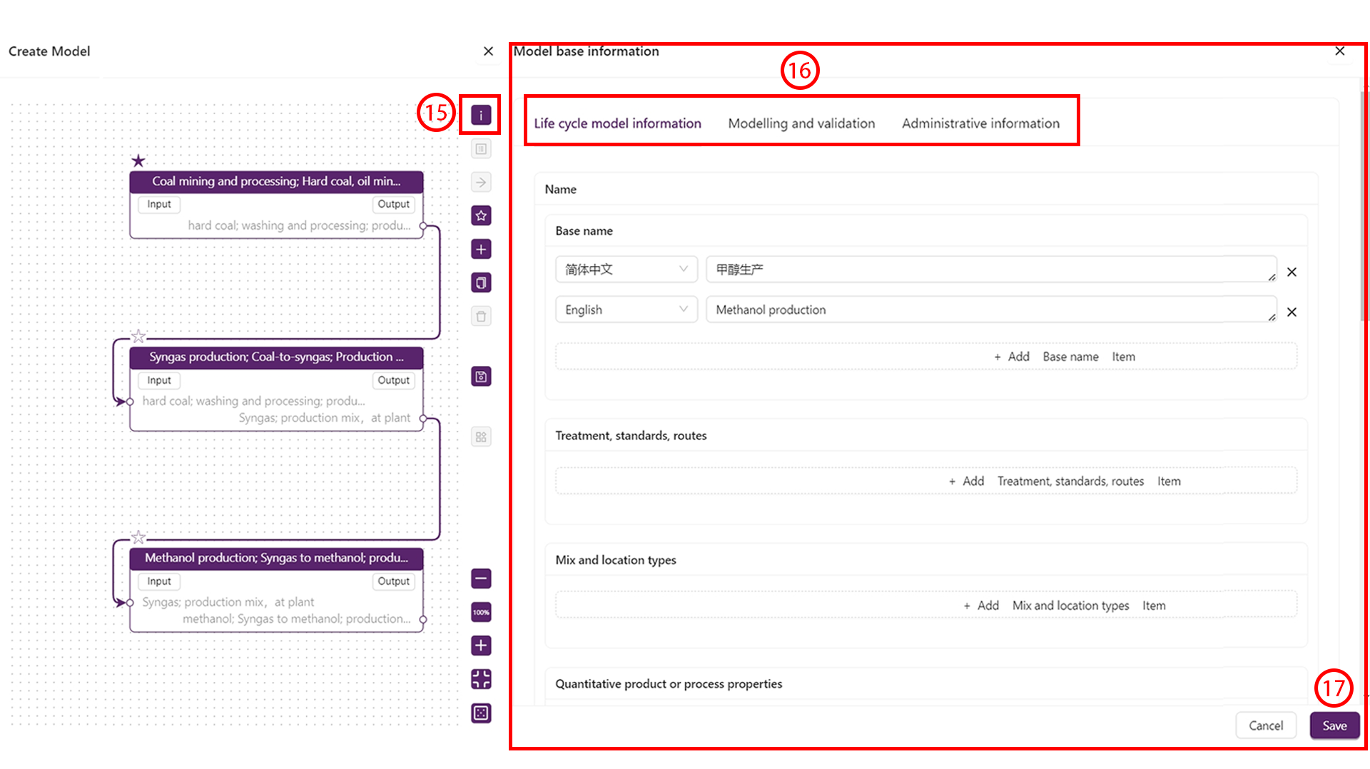
- Complete “Model information”, “Modelling & validation”, and “Management information”.
- Review the Model results panel, then save.
Models composed of multiple unit processes can be reused as processes. After saving, they appear in both “Models” and “Processes”.
Create a flow
- Open My Data → Flows and click
+.
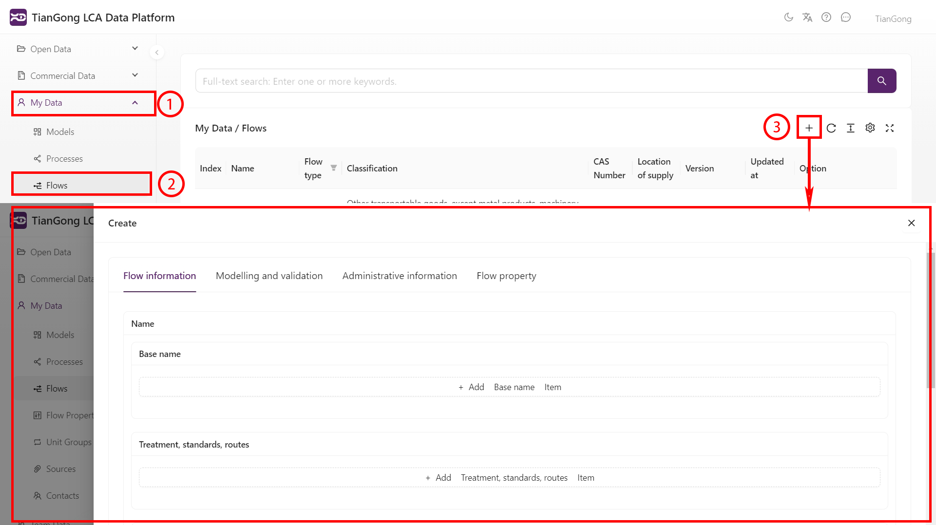
- Fill in “Flow information”, “Modelling & validation”, and “Management information”.
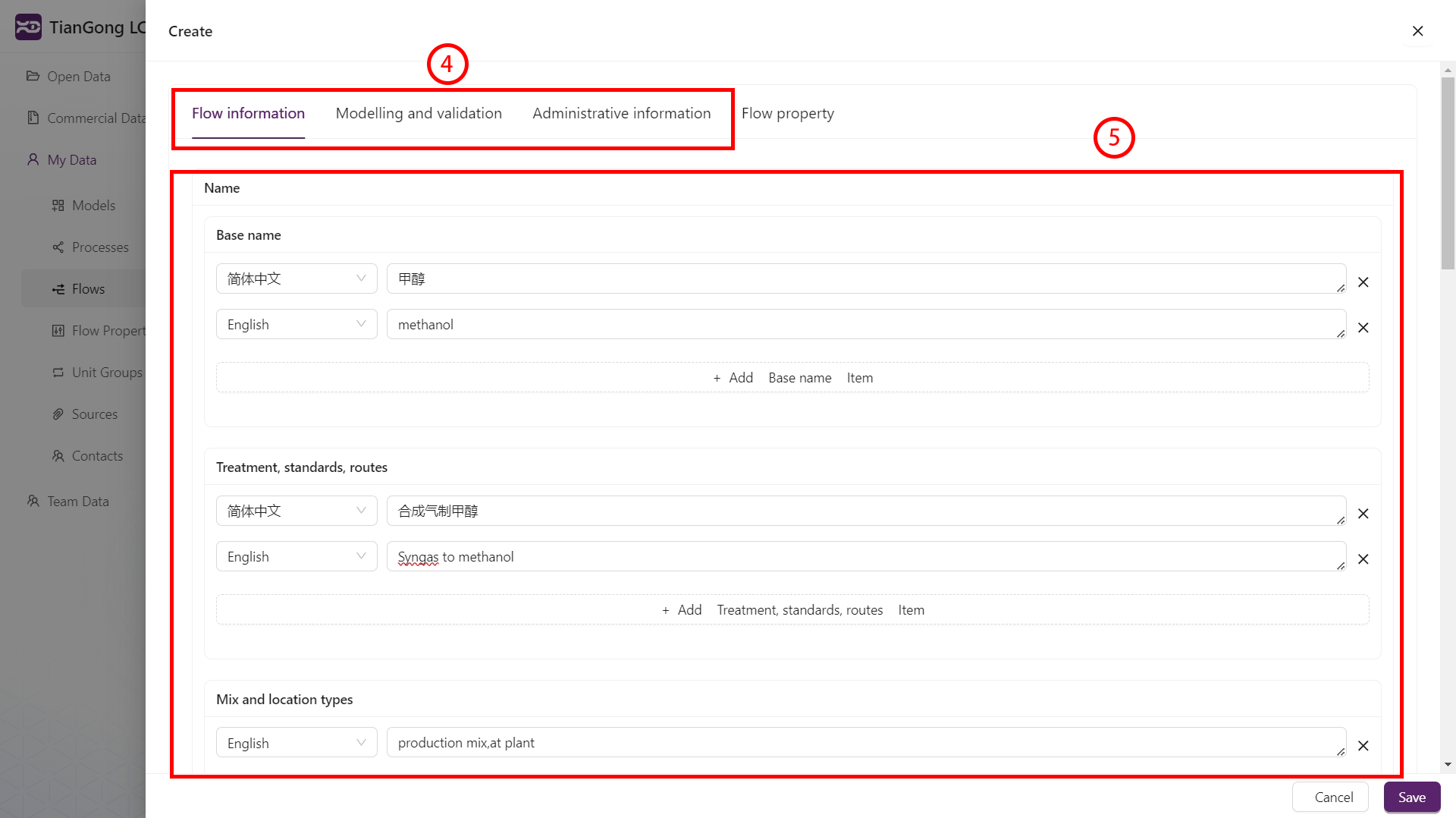
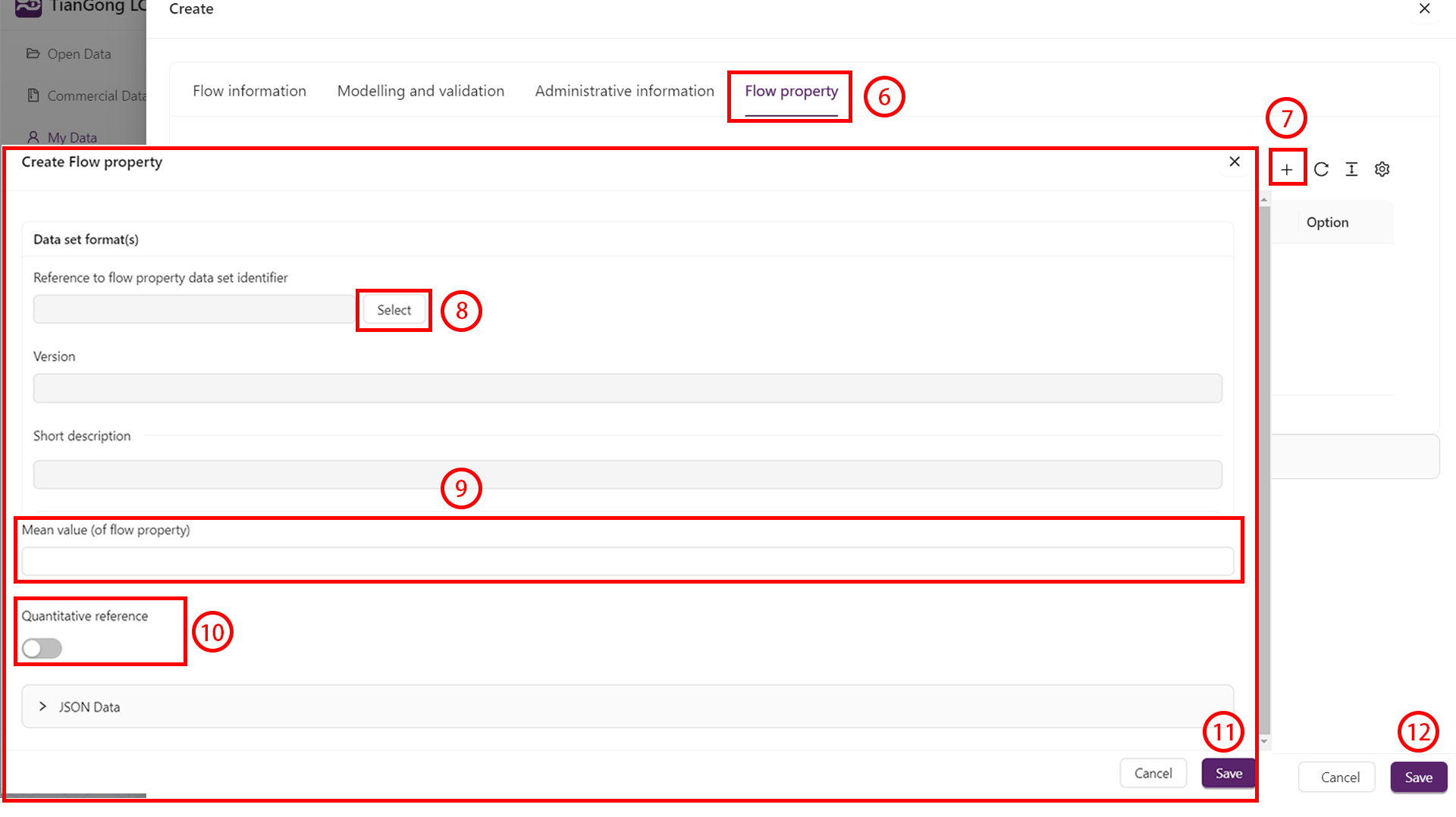
- Under Flow properties, click
+to select or create properties, then provide the values and quantity settings. - Save the flow.
Create a contact
- Open My Data → Contacts and click
+. - Provide names, emails, and optional organisation details (link to an existing team if needed).
- Save so the contact can be referenced elsewhere.
Create a source
- Open My Data → Sources and click
+. - Fill in authors, title, publication details, year, and DOI/URL.
- Upload attachments under “Electronic document link” if applicable, then save.
Citations should follow standard academic formats. Example:
Liu J., Zhao J., Wei H., et al., Comparative environmental assessment of methanol production technologies: A cradle-to-gate life cycle analysis. Energy Conversion and Management, 2024, 302:118128.
Unit groups & flow properties (advanced)
Custom unit groups or flow properties can introduce conversion issues or LCIA failures. Use them only when absolutely necessary.
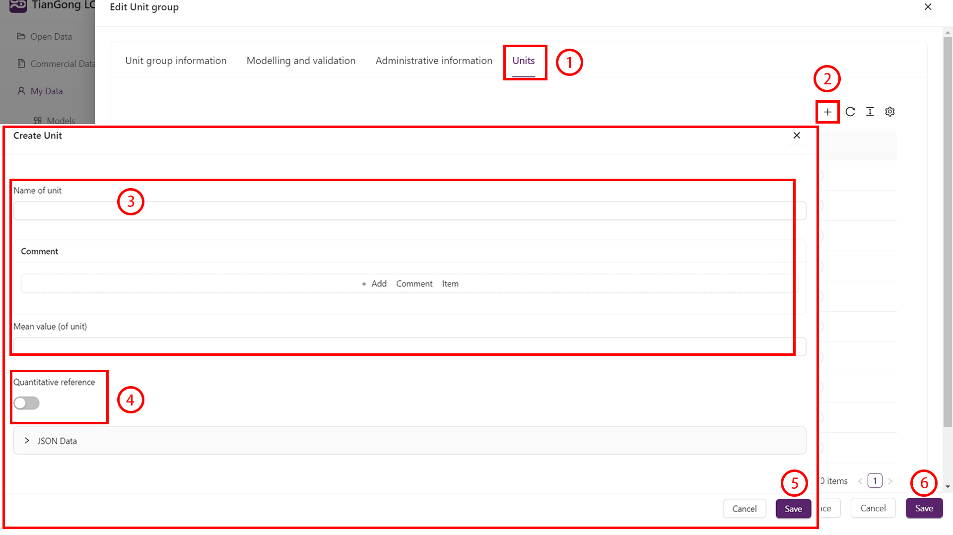
Create a unit group
- Open My Data → Unit groups and click
+. - Fill in “Unit group information”, “Modelling & validation”, and “Management information”.
- Under Units, add each unit, define conversion factors, and mark the reference unit (e.g.
kgin a mass group).
Create a flow property
- Open My Data → Flow properties and click
+. - Complete “Flow property information”, “Modelling & validation”, and “Management information”.
- Align the property category (technical / chemical / economic / other) with a compatible unit group.
- For updated datasets, link the previous version in “Management information”.
Data validation & publish
- Save drafts frequently to avoid losing progress.
- Run
Data checkon the process or model editor to validate required fields and references. - Submit for review and monitor the status via the message centre or the filters described in Data Review.
- Collaborate by contributing the dataset to your team if others need to continue the work.